Configuring Vlans on a Draytek Vigor 2130 N
Before I begin, I really need to thank the guy from the Vigor 2130 Google Code page, I did not get his name, but without his help and patient it would never succeeded. So thank you!
When I bought the Draytek Vigor 2130n one of the requirements I had was VLAN support. I could imagine that in the near future I was willing to split up my home network in multiple networks (VLANs). So I was amazed when the time was finally there, that the VLAN support I was looking for wasn’t supported through the web interface. I even read the manual and there was just no way to configure VLANs the way I wanted. So as my last resort I went to the Google Code page and asked for help. Below you find a summary of how I configured my vlans. Before we actually begin, let me explain what I wanted to built. My idea was to get some experience with the Vyatta firewall which has a free community edition and since I have a couple of services which are accessible through the Internet I planned to create a DMZ, a LAN and a Transit zone. If we place it in a logical view, it looks something like this.
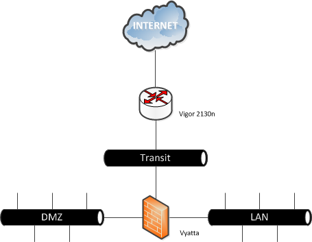
As you can see, there are three different zones, so I needed to create at least 3 VLANs. Later on you’ll notice, that the Vigor handles the WAN zone (connection between de router and the modem/Internet) also as VLAN. To make everything just a little more complex the VLANs should be available on a smart switch ( Netgear GS108t v2) too. This smart switch is connected on the Vigor 2130 on LAN port 4, so I needed to make this port a trunk(multi-vlan port), the other three LAN ports, could be placed in the LAN network. Before we dive any deeper, here are the details for the VLANs, the VLAN ID and subnets. (I know that VLANs are a Layer 2 functionality, but to make the above situation work, we also need to make some Layer 3 changes, which I will explain later).
| VLAN | ID | Subnet |
|---|---|---|
| Transit | 10 | 192.168.1.0/24 |
| LAN | 20 | 10.0.0.0/24 |
| DMZ | 30 | 172.16.0.0/24 |
| WAN | 2 |
Unfortunately for those of you who like the mouse, all the settings are made through the CLI. So login to the router with telnet or SSH, depending on your configuration. The VLAN settings are placed in the “vlan” and “vlan_port” files under “/etc/config/switch/”. The “vlan file”, contains the VLAN ID and which ports are member of this VLAN. The membership is a binary filter.
| 128 | 64 | 32 | 16 | 8 | 4 | 2 | 1 |
|---|---|---|---|---|---|---|---|
| x | x | LAN4 | LAN3 | LAN2 | LAN1 | WAN | x |
As I mentioned before, LAN Port 4 is becoming a trunk (multi-vlan) port for VLAN 20 and 30, the other LAN ports are becoming a member of VLAN 20 (LAN). After configuring the file, with “vi”, it look like this.
2/2 10/32 20/60 30/32
For example in case you didn’t see where the numbers are coming from, VLAN 20 has LAN ports 1,2,3 and 4 in it. So if you fill in the table.
| 128 | 64 | 32 | 16 | 8 | 4 | 2 | 1 |
|---|---|---|---|---|---|---|---|
| x | x | LAN4 | LAN3 | LAN2 | LAN1 | WAN | x |
| x | x | yes | yes | yes | yes | no | x |
Now count the fields that contain yes, with the above values and you will find out, where the number 60 is coming from. So far the “vlan file” configuration, now we need to set the specific port details for the vlans, which can be done in the “vlan_port file”. The vlan_port file, contains the following information.
- Port (1 – WAN, 2-5 LAN)
- VLAN Aware (Bring VLAN tag out)
- Ingress filter (Only accept the VLAN belong to this port)
- Frame Type (0 – Accept all frames, 1 – Accept tagged frames only, 2 – Accept untagged frames only)
- VLAN ID
There are only two options which need our attention for the above set-up. The VLAN Aware option, which we need for LAN port 4, cause this port is becoming a trunk (multu-vlan) port. The last port, sets the native VLAN of the Port, which is in our case 20. So after changing the file, it will look like this.
1/0/0/0/2
2/0/0/0/20
3/0/0/0/20
4/0/0/0/20
5/1/0/0/20
The most important thing is the last “1” just after the “5”, this makes port 5 (LAN Port 4) a trunk (multi-vlan) port. Now that that the VLANs are created, we can put devices in it. The only problem left is that the devices, cannot communicate with devices in other VLANs, let alone the Internet. So we need to create some gateways. The Vyatta firewall will take care of the routing between the different VLANs, to make sure the routing is working probably, I created rules which allow everything. (So I don’t go blind on a firewall deny rule). This is the picture, with the subnets and specific gateways in it.
 On the Vyatta firewall, I created a default routing to the Vigor. So every package which isn’t directly connected (DMZ/LAN/Transit), goes to 192.168.1.254. Before we actually can reach this address on the Vigor, we need to add it. This can be done in the “network file”, which is placed in /etc/config. We need to change the IP-address and the interface name, the number after the period tells to which VLAN this interface belongs to. So ifname ‘eht0.10’ belongs to VLAN 10. The corresponding part after changing the file.
config interface lan option ifname ’eth0.10’ option proto static option ipaddr ‘192.168.1.254’ option netmask ‘255.255.255.0’ option detect 0 option type ‘bridge’ option pppoe_pass 0
For the Vigor we need to do the same thing, cause every packet which is for the DMZ or LAN cannot be delivered directly. So we create two routing rules, to make sure the packets are delivered correctly. This can be done in the web interface or in the CLI.
 In the CLI, it can be done by editing the “s_route file” which is also placed in the /etc/config directory.
config static-route sr0 option enable ‘1’ option net ‘172.16.0.0’ option mask ‘255.255.255.0’ option gateway ‘172.16.1.253’ config static-route sr1 option enable ‘1’ option net ‘10.0.0.0’ option mask ‘255.255.255.0’ option gateway ‘172.16.1.253’
Finally it is time to reboot the router and make the settings active! If everything worked out well, you can now send packages between the VLANs. There is only one thing left. You can’t send packages to the Internet. There are two reasons why sending packages to the Internet doesn’t work.
- The IP-Tables firewall is blocking “unknown” subnets, in this case the DMZ and LAN.
- There is no natting done, so packages(responds) can never find there way back home.
First we fix problem one. This can be done, by the following command.
iptables -I FORWARD -s 172.16.0.0/24 -d 0.0.0.0 -p ALL -j ACCEPT iptables -I FORWARD -s 10.0.0.0/24 -d 0.0.0.0 -p ALL -j ACCEPT
With the following command, you can check if the entries appear in the FORWARD list.
iptables -L FORWARD
For the second problem, we add both subnets to the NAT list. With the following command you can see the current NAT list.
iptables -t nat -L zone_wan_nat
You will see that only the subnet which is known by the router is added to the list. So we need to add the DMZ and LAN zone manually.
iptables -t nat -I zone_wan_nat -s 172.16.0.0/24 -d 0.0.0.0 -j MASQUERADE iptables -t nat -I zone_wan_nat -s 10.0.0.0/24 -d 0.0.0.0 -j MASQUERADE
Now the list, will look like.
Chain zone_wan_nat (1 references) target prot opt source destination MASQUERADE all – 192.168.1.0/24 anywhere MASQUERADE all – 172.16.0.0/24 anywhere MASQUERADE all – 10.0.0.0/24 anywhere
Unfortunately the iptable settings are gone after a reboot. These settings can probably be added in the following two files, but I haven’t tested it yet.
- /etc/firewall.user
- /lib/firewall/uci_firewall.sh
If you have modified these files, please let me know. Have fun with your VLAN enabled Draytek Vigor 2130