Mikrotik VLAN Switching Without Bridging
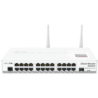
One of the greatest networking vendors for homelabs is in my opinion Mikrotik, they offer great (often enterprise) features for a very compelling price. On the other hand it can be a bit daunting to configure and the firmware releases aren’t always equally stable. Last week I upgraded in my homelab one of two RB2011UiAS’s, which are I think the most popular Routerboards, for a CRS125, cause I was in need of more 1 gigabit ports. Previously I did all my VLAN configuring using bridging, which works, but there is a faster way, by using the internal switch chip, instead of the CPU. So this upgrade was the perfect case for me, to change this. Because this can be a bit hard in understanding and most tutorials on the web are about bridging. I decided to do a little write-up, about how this can be done without bridging. I will take it even a bit further and making sure we have a management address configured on the switch and we can use the wireless network. Before we actually start, a bit of understanding how the internals work, it is based on this site, but I will try to clarify it even a bit more.
A small disclaimer; the workings are described as far as my understanding goes, if you find any mistakes, please let me know!
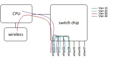
In the below picture you find a simple logic representation of the inner workings.
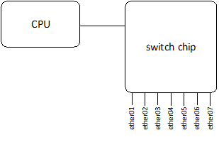
The physical switch ports are connected to the switch chip and the switch chip has also a connection to the CPU. The CPU is where all the clever things happen, think about, routing, bridging, nat(-ting?), etc. So when we created simple interfaces for bridging the flow will go like the picture below.
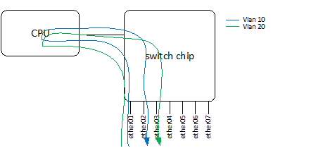
There is nothing wrong with this and gives us great flexibility, but when you only need layer 2 switching this generates a lot of unnecessary pressure on the CPU. So this can be done more efficient by connecting the right interfaces on the switch chip, this way the traffic won’t need to pass the CPU, which is far more efficient. We can talk about “wire speed” here.
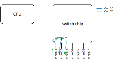
In the picture above interface ether01, ether02 and ether03 are connected with each other and ether01 is a trunk (=multi-vlan port), probably an uplink and ether02 and 03 could be access ports which go to a vlan unaware device a PC or printer for example. This is the basic idea what we are going to set-up, although we make it a bit more complex. We want a management interface which must also be routable (i.e. for NTP and updates) and we want to connect the wireless. So let’s say for example we have 4 vlans.
- Servers – vlan 10
- Clients – vlan 20
- Wireless – vlan 30
- Management – vlan 40
The interfaced are used as follow:
- ether01 – Uplink / trunk
- ether02 – trunk (vlan 40, vlan 10) (i.e. ESX)
- ether03 – access port vlan 10 (i.e. NAS)
- ether04 – access port vlan 20 (i.e. desktop)
What we would like to accomplish would look like this, assuming that we only need layer 2 switching for the vlans and that only the management vlan is routable.
Be aware that in this set-up devices in different vlans aren’t able to communicate with each other! Therefore you need a router or make a routable interface, like the management one.
The first step is to connect the interfaces to each other, this can be done by choosing a master-port and make the other interfaces slaves of it, in this example we choose to make “ether01” the master port.
[admin@MikroTik] > interface ethernet
[admin@MikroTik] /interface ethernet>set numbers=1,2,3 master-port=ether01

[admin@MikroTik] > interface ethernet print
Flags: X - disabled, R - running, S - slave
 #    NAME    MTU  MAC-ADDRESS       ARP        MASTER-PORT       SWITCH
 0 R  ether01 1500 D4:CA:6D:CE:3C:20 enabled    none              switch1
 1  S ether02 1500 D4:CA:6D:CE:3C:21 enabled    ether01           switch1
 2 RS ether03 1500 D4:CA:6D:CE:3C:22 enabled    ether01           switch1
 3  S ether04 1500 D4:CA:6D:CE:3C:23 enabled    ether01           switch1
After this we can start with the vlan configuration, which also consists of a few steps and is done differently than you see at more regular switch vendors (i.e. Cisco, HP). We start deciding which vlans are needed on which port, important to see here is that switch1-cpu is actually a port and will forward the traffic to the CPU. So the management and the wireless vlan are needed on the switch1-cpu port.
[admin@MikroTik] > interface ethernet switch vlan
[admin@MikroTik] /interface ethernet switch vlan> add ports=ether01,ether02,ether03 vlan-id=10
[admin@MikroTik] /interface ethernet switch vlan> add ports=ether01,ether04 vlan-id=20
[admin@MikroTik] /interface ethernet switch vlan> add ports=ether01,switch1-cpu vlan-id=30
[admin@MikroTik] /interface ethernet switch vlan> add ports=ether01,ether03,switch1-cpu vlan-id=40
Now we need to decide which ports are carrying “tagged” vlan traffic and which ports are receiving “untagged” traffic. In this example “ether03” and “ether04” will receive untagged traffic. To make this traffic go to the right ports we need to “tag” this traffic when we receive (ingress) it.
[admin@MikroTik] > interface ethernet switch ingress-vlan-translation
[admin@MikroTik] /interface ethernet switch ingress-vlan-translation> add ports=ether03 new-customer-vid=10
[admin@MikroTik] /interface ethernet switch ingress-vlan-translation> add ports=ether04 new-customer-vid=20
[admin@MikroTik] /interface ethernet switch ingress-vlan-translation> print
 0   ports=ether03 service-vlan-format=any customer-vlan-format=any new-customer-vid=10 pcp-propagation=no sa-learning=no
 1   ports=ether04 service-vlan-format=any customer-vlan-format=any new-customer-vid=20 pcp-propagation=no sa-learning=no
Now all the traffic that is coming in the switch is “tagged” correctly, we can decide where the “tagged” traffic may go (egress). We also need to specify the “switch1-cpu” port here, cause for the “switch chip” it is just a port, where traffic can go.
[admin@MikroTik] > interface ethernet switch egress-vlan-tag
[admin@MikroTik] /interface ethernet switch egress-vlan-tag> add vlan-id=10 tagged-ports=ether01,ether02
[admin@MikroTik] /interface ethernet switch egress-vlan-tag> add vlan-id=20 tagged-ports=ether01
[admin@MikroTik] /interface ethernet switch egress-vlan-tag> add vlan-id=30 tagged-ports=ether01,switch1-cpu
[admin@MikroTik] /interface ethernet switch egress-vlan-tag> add vlan-id=40 tagged-ports=ether01,ether02,switch1-cpu

[admin@MikroTik] /interface ethernet switch egress-vlan-tag> print
Flags: X - disabled, I - invalid, D - dynamic
 #   VLAN-ID TAGGED-PORTS
 0        10 ether01
             ether02
 1        20 ether01
 2        30 ether01
             switch1-cpu
 3        40 ether01
             ether02
             switch1-cpu
vlan 10 and 20 should be working by now. So now we only need to do something clever with the management and the wireless. Let’s start with the management. We create a vlan interface, which can be handled by CPU.
[admin@MikroTik] > interface vlan
[admin@MikroTik] /interface vlan> add name=vlan40 interface=ether01 vlan-id=40
Connect the management IP to this interface.
[admin@MikroTik] > ip address
[admin@MikroTik] /ip address> add address=10.10.10.10 netmask=255.255.255.0 interface=vlan40
To make sure this interface can be used for updating ntp or download updates we need to make it routable. (assuming the router address is 10.10.10.1)
[admin@MikroTik\] > ip route
[admin@MikroTik\] /ip route> add dst-address=0.0.0.0/0 gateway=10.10.10.1
From now on this IP could be used for management. The last step is the wireless, for this we also need to make a vlan interface, which we will bridge to the wireless interface. (for as far as I know this is the only way).
[admin@MikroTik\] > interface vlan
[admin@MikroTik\] /interface vlan> add name=vlan30 interface=ether01 vlan-id=30
Create a bridge
[admin@MikroTik] > interface bridge
[admin@MikroTik] /interface bridge> add name=br-wireleass
The last step is to actually bridge the wireless with the vlan interface
[admin@MikroTik] > interface bridge port
[admin@MikroTik] /interface bridge port> add bridge=br-wireless interface=vlan30
[admin@MikroTik] /interface bridge port> add bridge=br-wireless interface=wlan1
That’s all! Hopefully it was any helpfull and will give you a clear understanding how things work.
Update 2015-07-15: Check this awesome Youtube explanation by David Gonzalez