Building an Awesome Led Cube 8x8x8

It has been a long time since I posted something really “techie” out here. In the mean time I was however busy with a very technical project at least is was for me. It had to do with “digital” electronics and Microcontroller(s), while this stuff is not completely new for me, it was at least a bit rusty. Sometimes (more than sometimes in my case), you see something on the Internet which is extremely cool and you can resist it get it yourself. This was the case when I accidentally saw this YouTube video.
Call it “nerdy” or whatever you want, I thought this was cool, so I went to the Instructable site and started building one myself. First the small (4x4x4) cube to practice a bit and after some lessons learned, I started building the big 8x8x8 cube. Below you find some pictures of the 4x4x4 cube, the hardest part of this cube was to order the right components, before you can order the right components it is wise to read the instructable and to understand the inner workings of the cube. Some things I’ve learned from the 4x4x4
- Don’t use S39, it will oxidize and give nasty brown spots on your cube, unless you’re willing to clean these spots with some vinegar, don’t use it. Use resin core solder instead.
- Test every LED before soldering it into the cube.
- Practice soldering on the PCB, especially for the 8x8x8, the guys on the instructable site, have some good vids about it.
- Just check and double check every connection you make, it can save you a lot of troubles.
- Read the specifications of the components, especially when you choose other components then described in the tutorial.
- Just start and don’t give up!
The 4x4x4 cube isn’t that hard to make, especially when you discover how it actually works. I think it should be doable in about two days, it took me about a week, but that was because I used an Atmega324PV for my first run, unfortunately I didn’t read the specs well enough to see that this microcontroller wasn’t working with 14Mhz. So after figuring this out, thanks to the guys of avrfreaks I replaced it with an Atmega32.

Finally the 4x4x4 looks like this:
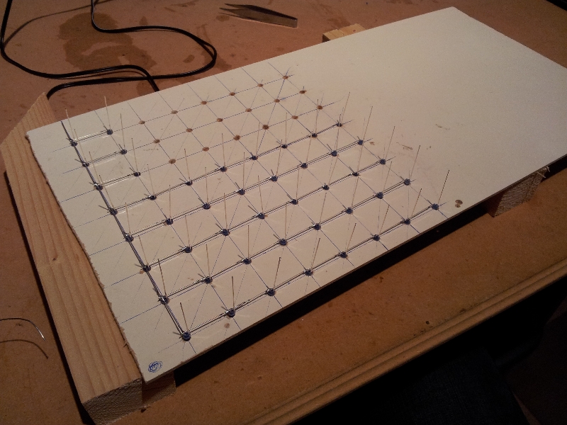
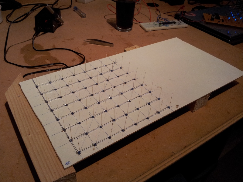
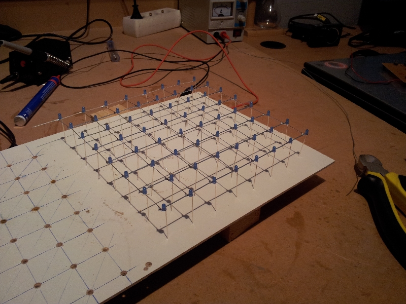
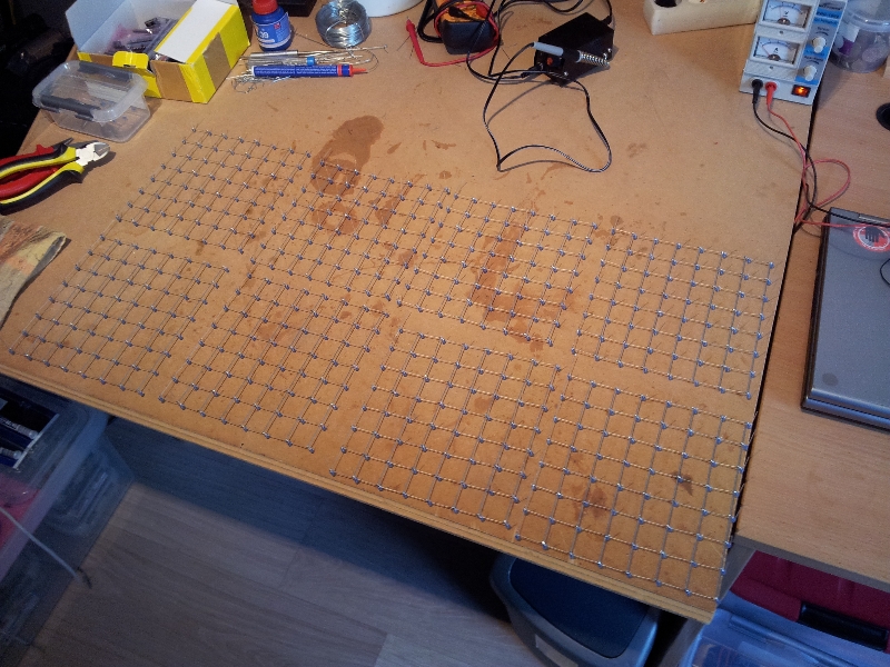
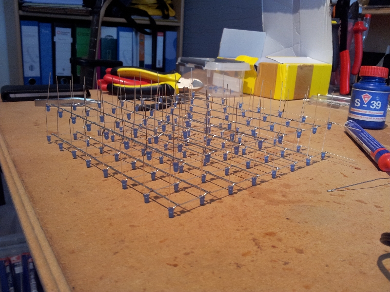
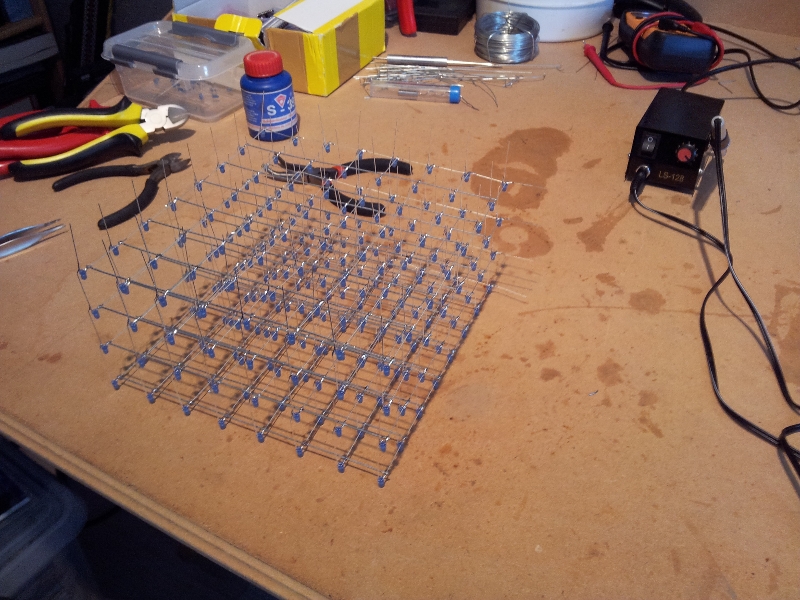
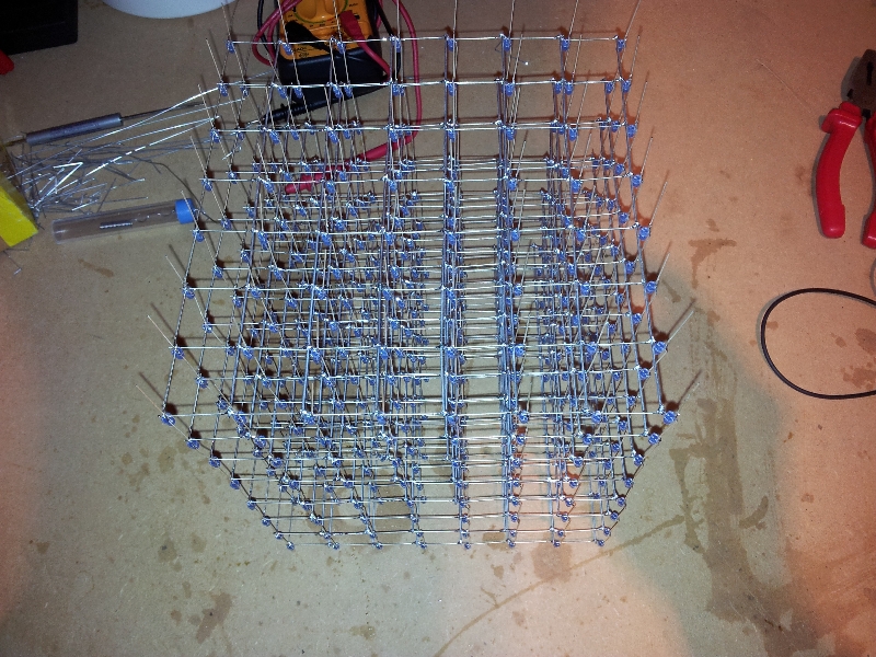
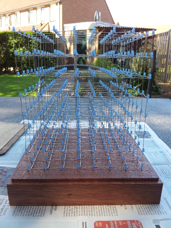
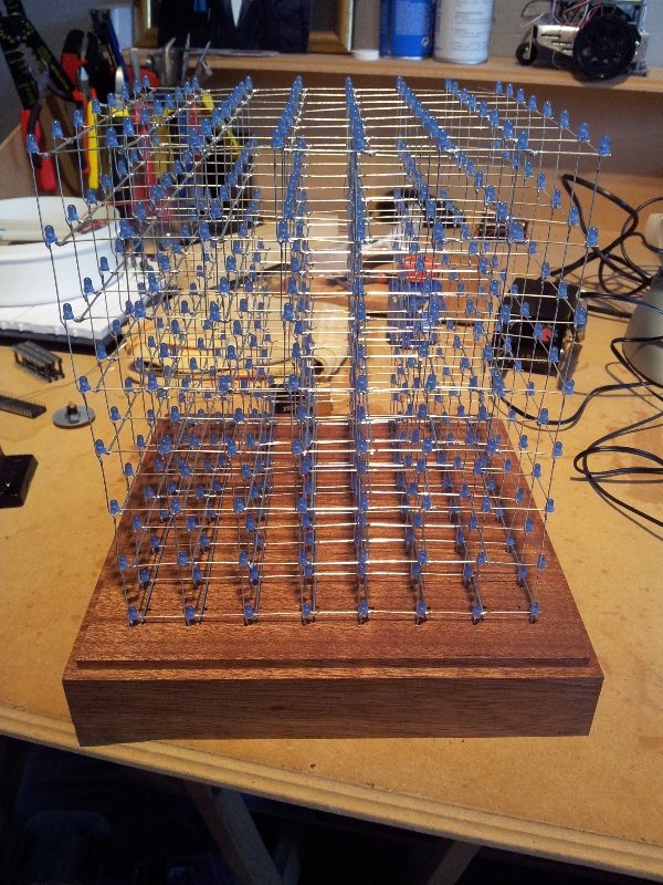
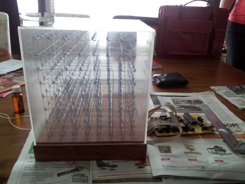
Now the 4x4x4 cube was working, it was time to start with the big 8x8x8 cube. The first part, just like the 4x4x4 is to soldering the LED’s to create the layers and eventually the cube. This is not a very hard task, but due the amount of LED’s it takes a while.

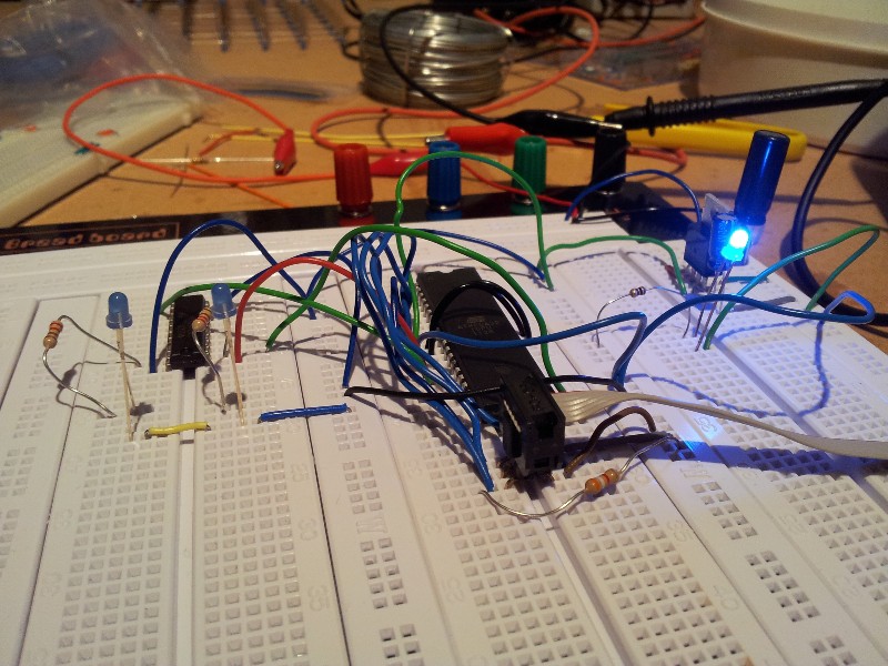
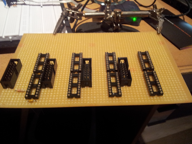
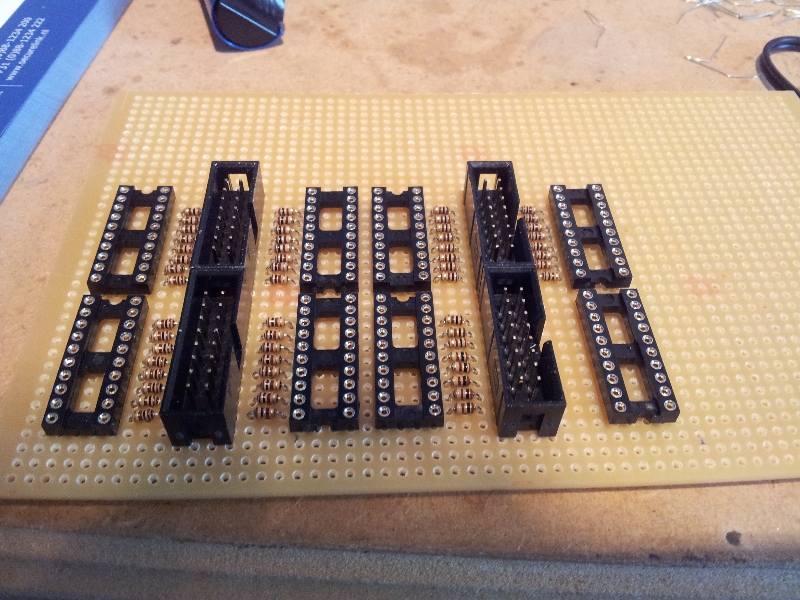
Now that the Cube was done, I took a look at the “latches” or “flip/flops”, to see how they actually works, I understood the theory, but it is always better to practice. This give me a better understanding about how the inner-workings of the cube works. After all it is a nice educational project :-)
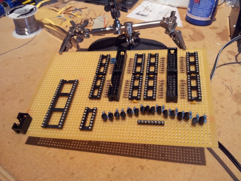
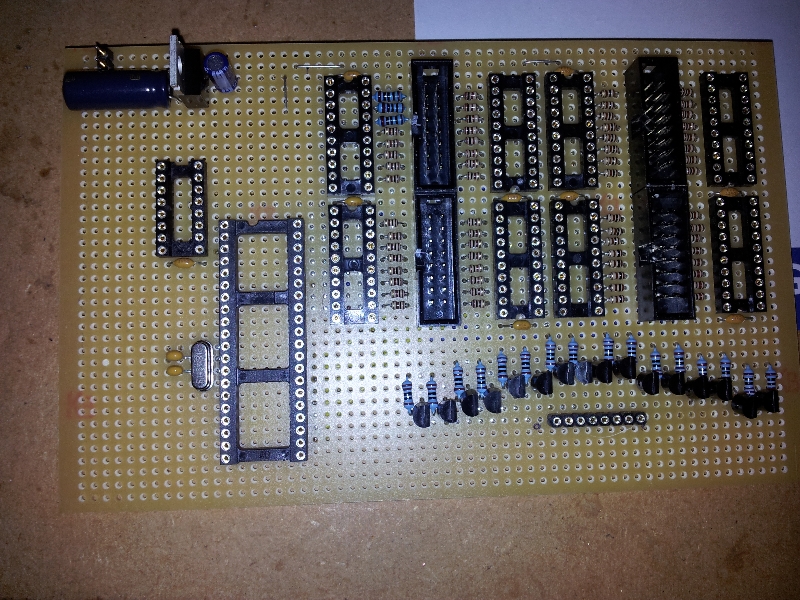
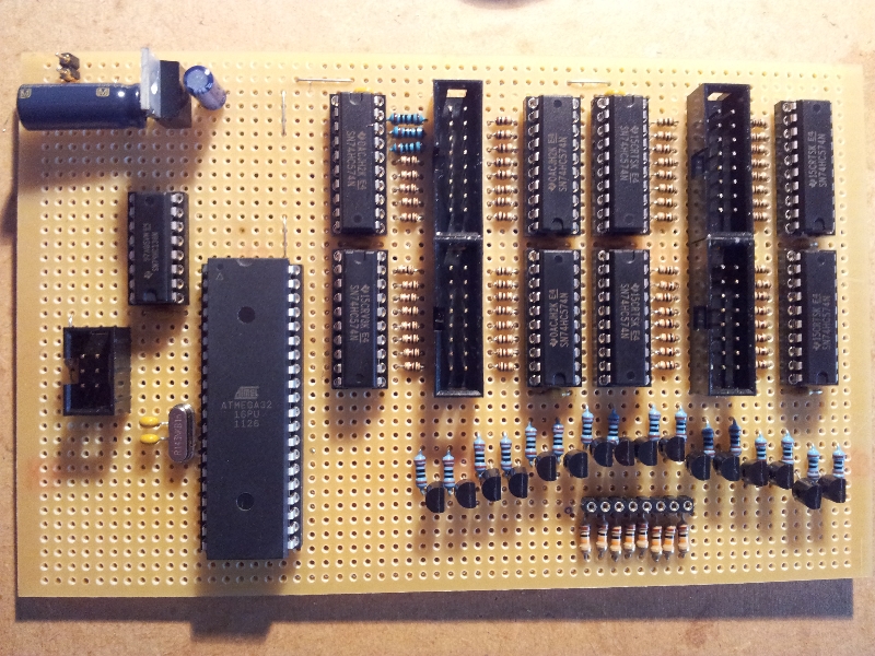
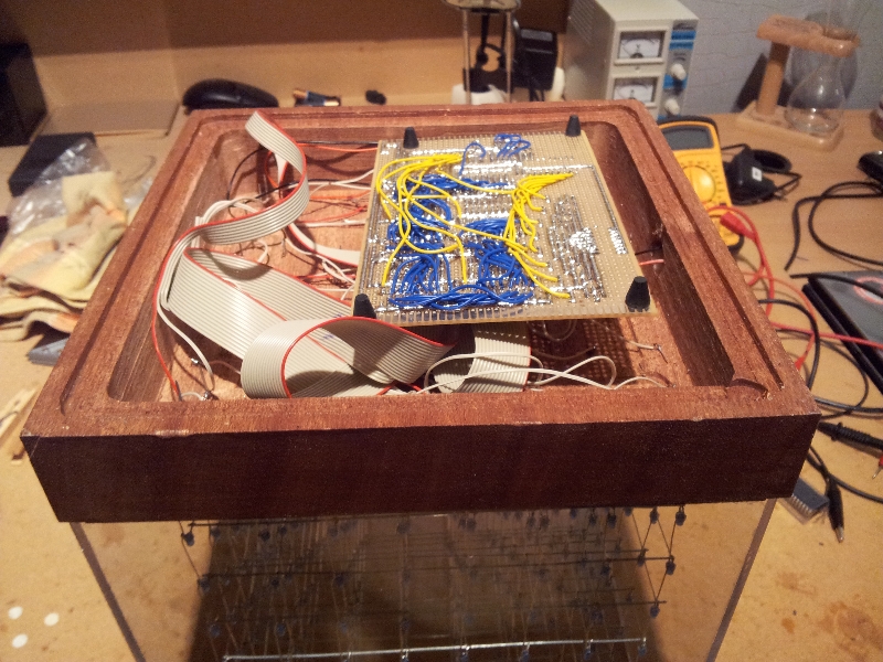
Now I knew how the cube was working, I was able to design the PCB. The basics of the design came from the instructable site, but my design was a bit different, I had not exactly the same components (especially the male connectors) and I was not planning to use an RS232 (serial) connection. So my goal was to make the design fit on a single PCB. This wasn’t as easy as I thought, but I managed it.
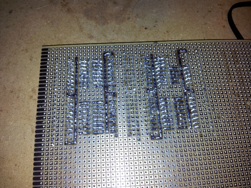
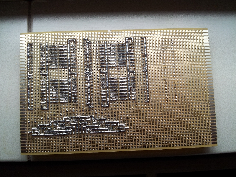
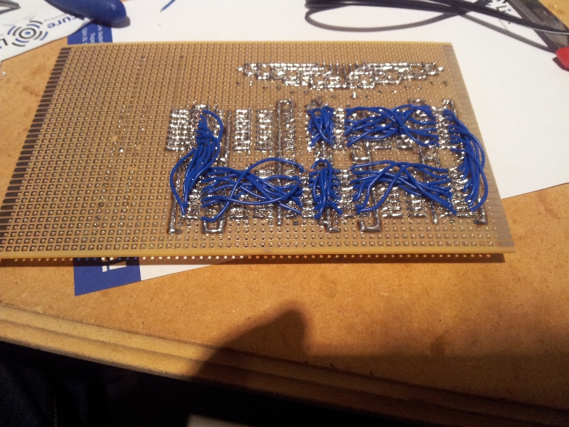
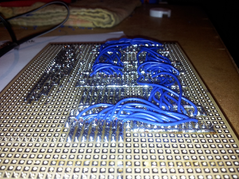
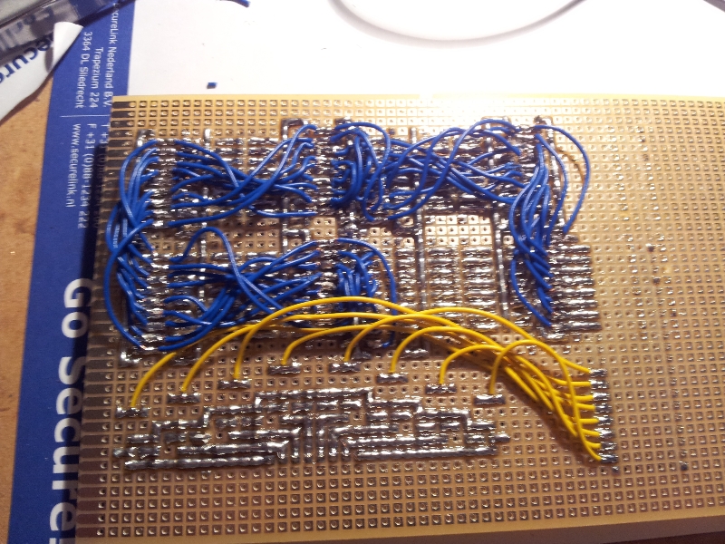
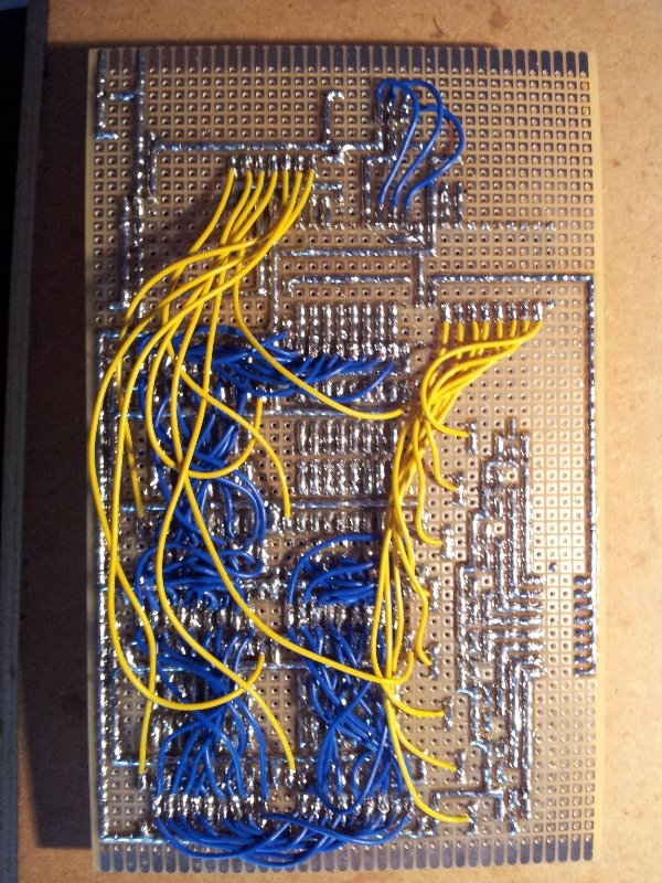
One of the best tips from the tutorial was to use “power” and “ground” lines all over the PCB, so components can be easily attached. There was only one small thing that seems an good idea, but turned out not to be or at least give me some extra work. I turned the 3-to-8 Line decoder, so that I could solder straight lines between the microcontroller and the line decoder. So the input of the line decoder (A1, A2, A3) where connected to port B (B2, B1, B0) on the microcontroller, in precisely that order. This means that I had to re-map the value between those components e.g. sending 3 (binary low to high) 110 to B0-B2, would turn out to be 6 on the line decoder (011 (A1-A3)). It was not to hard to solve in the code, but the code would look simpler if I didn’t turn around the line decoder on the other hand it keeps the PCB soldering simple :). Last thing about the PCB, it took a lot more time to solder, than I imagined.


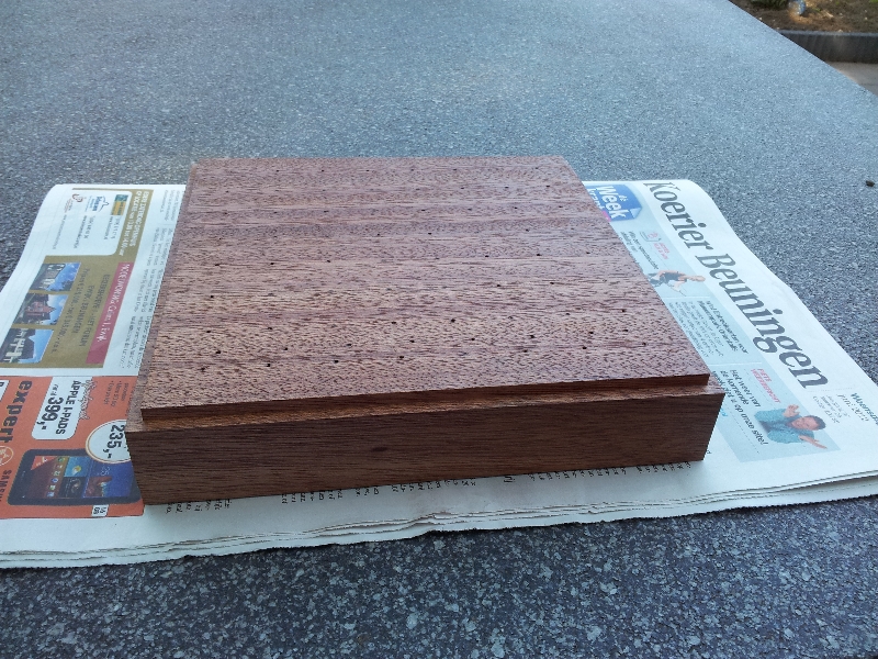
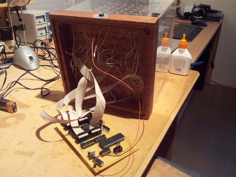
Now that the PCB was ready, there where two things left a base for the cube and the connection between the cube and the PCB. For the base I asked someone to help me, since I’m not a carpenter and I would the base to look cool and be the finishing touch of the cube, well I think that has be accomplished.

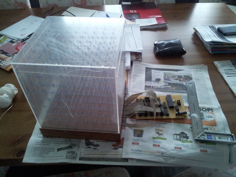
The last part of the cube was the connection between the cube and the PCB and of course programming the microcontroller and not to forget, especially for protection I created a perspex case which fitts nicely around the cube.
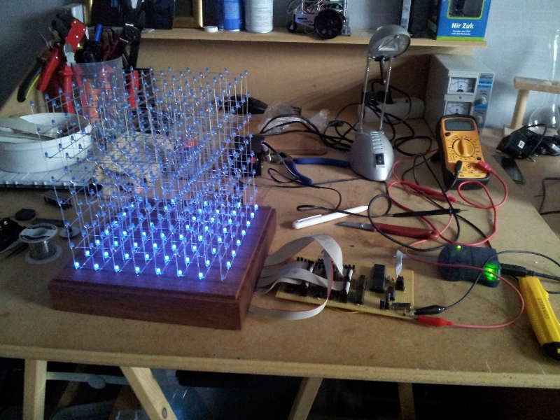
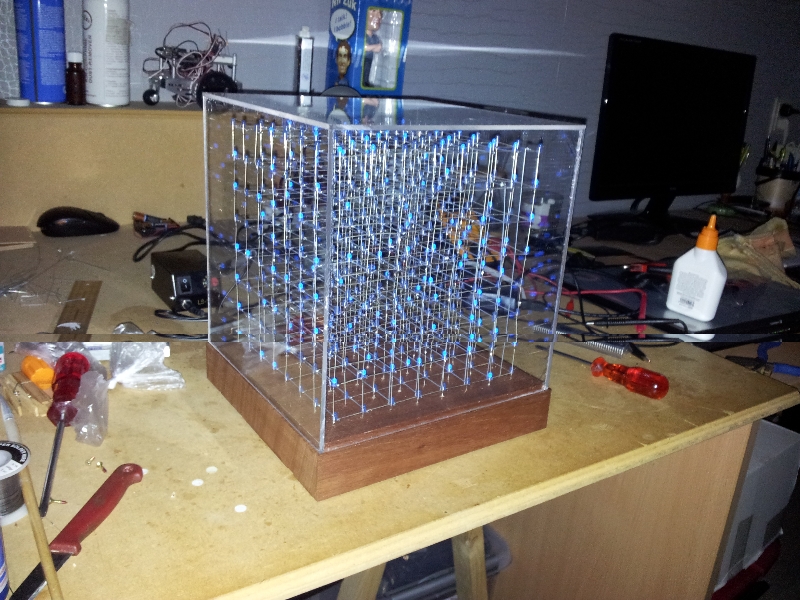
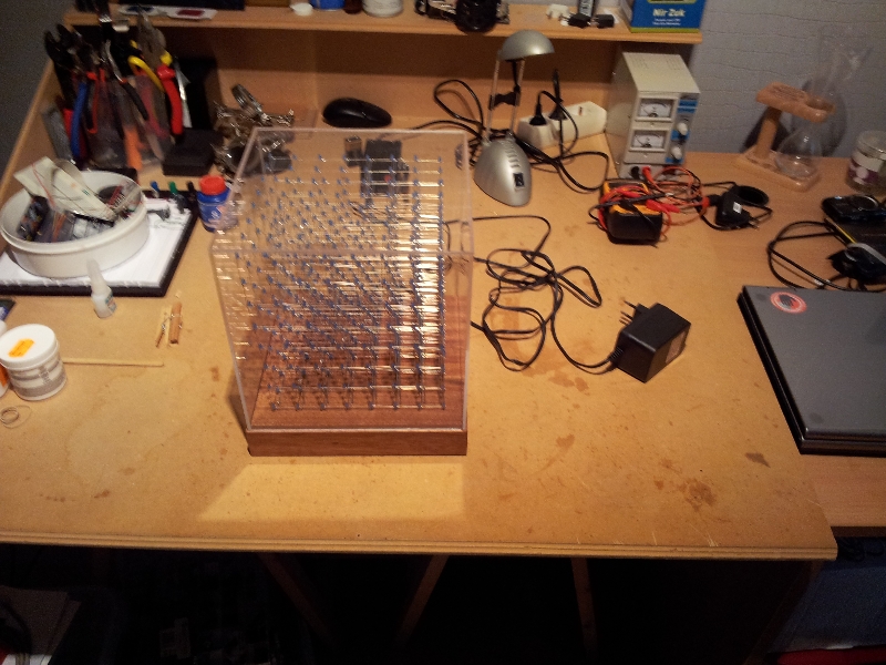
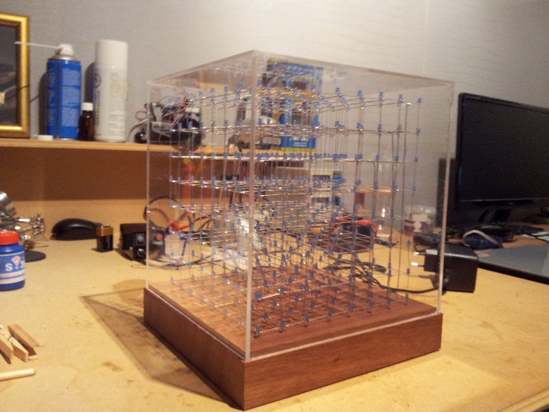
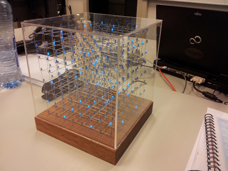
And of course here it is how it finally looks in action. The reflection you see is from the perspex, luckily I can easily remove it whenever I want.